Corgi Car PCC Truck Installation
The work of Bill Becwar of Wauwatosa, Wisconsin.
Photos and diagrams by Bill Becwar.
Truck Installation
To Install a truck in a Corgi car may be difficult, but It isn't brain surgery, exactly, just a little fabrication and layout.
PARTS NEEDED:
- 1 - brass strip 1/2" x 0.040" (about 1 ft)
- 6" - 4-40 threaded rod (Hobby USA model airplane parts)
- 2 - 4-40 T-nuts (You can use regular nuts, but these are easier)
- 9 - 4-40 brass nuts (also can use nylon insert nuts)
- 3 - 4-40 x 1/4" machine screws (brass or steel)
- 1 - 4-40 nylon screw (if using two rail power)
- 3 - #4 brass washers
- 1 - pole hook (PCC)
- 1/4" - 1/8" brass tubing (for trolley pole wiring, if used)
- 1 - trolley pole (wheel or shoe)
- 1 - motor truck set (Clark B2
about 1-1/4" of #26-30 wire (for trolley pole wiring, if used)
Note that much of the non-model stuff is straight from the hardware store. The 4-40 threaded rod and T-nuts are easiest to find in the model airplane section of the Hobbytown hobby shop.

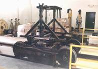
The first challenge is how to get the Corgi apart without damaging anything important. The trucks come off with screws (see photo #1 ), but the bottom won't seem to come apart for anything. The floor is actually two pieces, the outer, bottom piece and the inner seats and interior details piece. We have to remove the outer piece first. The trick here is to look in the windows; the four mounting studs from the car roof are permanently press fit into plastic bosses in the lower floor. They will not pull out, but you can get around this by hand drilling into the bottom floor right under each of the bosses with a good sized drill (say 1/4")(see photo #2 ). You can almost see little depressions in the metal where the thicker plastic at those spots shrink a tiny amount extra when cooling. The object is not to drill through the floor, but to weaken the outer floor right at those mountings.
Editors Note: We have prepared a template that can be run on a printer. It will align the location of the mounting stubs. You can then use a Dremel tool with a fine cutting mill to cut around the post. It will leave a small 3/16" hole. Two can be used for extension posts to remount the floor, one will be eliminated when the motor truck hole is cut so it can be ignored, and the one to the rear of the car can be filled or capped.
To view a copy of the template CLICK HERE.
To download a copy of the template CLICK HERE.
Keep in mind some printers will distort this image. If the steps do not line up, adjust the size before printing a second copy using your computers "Page Setup". Some printers will truncate the image up to a half inch. We have included dimensions if you do not want to print the template.
I didn't have much trouble getting the floor loose by just bending the
floor panel a tiny bit to clear the headlight and retriever stud - at least
until I file that small slot at the back seat for easier assembly when
everything is attached. I was worried that popping the retriever out might
damage the paint. One way to remove the headlight without damage is to open
the car first, then use a needle nose pliers to start to turn the screw out
from inside the car. The entire headlight and screw assembly will usually
come out in one piece.
[If you would like to remove the Life Guard to prevent damaging it during floor removal you must "pop" the headlight lens out. Under it there is a screw that holds the Universal Life guard in place. Remove the screw and pull the life guard out. The Retriever holds the upper floor (seats) in place. If you are worried you will damage the finish of the model skip this. Otherwise pull the retriever out. Editor]
Now with a small screwdriver (and some thin wood or plastic to protect the body paint), pry up on the outside floor pan to pop each of the bosses off in turn(see photo #3 ). Once they are clear everything comes apart pretty easily, though you may have to gently bend the floor a bit to get it clear. You can then take a pliers and (carefully) break off the four Corgi mounting studs at the inside roof - we won't be using those.
Mark each truck center location by drilling a small hole in the inner floor (with the seats). This will provide a reference point for later work. Throw the outer floor away, mufflers, tailpipe and all.
Now you have a nice car body and a detailed inner floor - except that the floor is too thin and too flexible to support the trucks properly. I use strip brass to make a reinforcing frame for the truck mounts. This also allows having the trucks at near prototype height. First step is to file off any protrusions  on the plastic floor that will get in the way of either truck swing or the brass truck frame (see photo #4). Leave the raised round hole in on the plastic floor for the front body mounting stud - handy to have that insulated. For ease of assembly, file a notch in the very back of the rear seat to clear the mounting stud for the trolley retriever on the back of the car. A little thing, but it saves cussing later. While we will be mounting the floor to two studs connected to the roof of the car, note that it is really the plastic window material that holds up the floor, so the studs just allow you to pick up the car without the chassis falling off. That would be just a little too non-prototypical. on the plastic floor that will get in the way of either truck swing or the brass truck frame (see photo #4). Leave the raised round hole in on the plastic floor for the front body mounting stud - handy to have that insulated. For ease of assembly, file a notch in the very back of the rear seat to clear the mounting stud for the trolley retriever on the back of the car. A little thing, but it saves cussing later. While we will be mounting the floor to two studs connected to the roof of the car, note that it is really the plastic window material that holds up the floor, so the studs just allow you to pick up the car without the chassis falling off. That would be just a little too non-prototypical.
Note that the brass strip is split into two sections with a long part under the front of the car and a shorter section on top of the plastic floor right in the rear aisle between the seats (see photo #4 ) & (see photo #5). The rear power truck actually mounts to this brass strip, allowing a prototype floor height (mounting under the plastic floor makes the car too high). See the truck mount drawing, which is as close as I get to having a written design for this thing. I pretty much cut 'em to fit, using the holes already in the floor for the mounting screws. When you have your pieces fabricated, check assembly and then epoxy the three front truck frame pieces together (see photo #7) & (see photo #8 ) show the two brass strips and the Q-Car bolster assembled).
Make sure the rear mount holds the truck in the right spot, then expand the hole in the plastic floor to something around 1/2" (photo #9) - about the width of the aisle. The brass will cover this from above. You can paint the top of the rear brass strip to hide it inside the car.
Time for the body mounts. I copy the Corgi design to the extent of using studs inside the car - just move them out of the way and make the body removable. Easiest way I've found to put this together is with epoxy putty and T-nuts (which are actually meant for wood). Make the studs longer than you will need and cut them down later. Place the carbody upside down and support it so it is level (I like to use bubble wrap for this). Drill holes in a couple of popsicle sticks and temporarily mount them on the bottom of the plastic floor to other than the furthest hole forward and furthest hole back - the locations of the carbody mounting studs (see photo #4). Screw a T-nut onto the end of each stud and epoxy the T-nut to the roof in approximately the right locations. Slip the plastic floor onto the studs and use the extra stud length to align the exact location of the T-nut inside the car so the studs are straight up and down - mostly for a nice appearance, actually.
While the epoxy is curing, solder the truck power lead wires to the outer edges of the brass washers. If you will be using overhead, you can also make the 1/4" long brass ferrule out of 1/8" brass tubing and solder a wire between that brass tube and a #4 brass washer (see photo #9). You may have to drill out the tubing slightly for clearance of the trolley pole's 2-56 screw. I have always put the screw in from the top (or used a bit of threaded rod) on my poles so that I can take poles right off for packing the car away. Keeps the poles from getting bent or scratching the paint. This also allows immediate change out of a troublesome pole without opening the car up and playing with the wiring. While you have the soldering iron hot, make a nice connection between the Q-Car bolster and the brass strips to make sure that the front truck power pickup will work reliably.
Once the epoxy has set, remove the plastic floor and assemble the parts . If you use two-rail power, you can connect everything at this time, with one power lead going to the nylon screw in front of the rear truck and the other to the mounting screw behind the rear truck. Remember to check which side the insulated wheels are on - they have to be opposite each other for the two-rail power to work.
Car Wiring Diagrams
Overhead
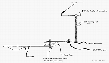
Two-Rail

The bare chassis will actually run, at this point. For testing, I'll sometimes use a nine volt transistor radio battery, which has just enough oomph to power the car slowly. This allows you to be sure the car runs in the right direction with positive power to the red motor wire. If using overhead power, the positive (red) wire will be loose for the moment. This part of the design allows you to convert a car from overhead to two-rail as needed. You can paint the top of the rear brass strip in the carbody at this point to hide it better inside the car.

Put the floor assembly on the studs (helps to start from the front) and mark the length to cut the body studs with the floor down all the way. You should be able to unscrew the threaded studs from the epoxied-in T-nuts. While the studs are out of the car body, modify the body by removing the fake plastic trolley pole and filing off that metal thing just behind hole for the trolley pole. Drill out the hole in the fake trolley pole mount cast into the car roof for a press fit of the 1/8" ferrule and glue it in place with a little CA from the inside. It helps to have the brass just a tiny fraction above the car roof, so the pole rides on a brass bearing/contact surface.
Note that there is no insulator on the brass trolley pole ferrule, so the cast aluminum car body will be hot to the positive overhead wire. I used to worry about stuff like that before I got the Zen nature. Took a surprisingly long time before I figured out that 12 volts is just not a problem for our plastic passengers. Also that the car runs just fine this way since the plastic floor insulates everything nicely. If a truck comes in contact to short against the carbody, far more things are wrong than an electrical fault.
You can add the trolley hook to the carbody now, too, just be careful not to knock it off while doing final assembly (see photo #10) shows modifications to the top of the car).

With the modifications done, turn the body over, screw in the cut-to-length studs (remembering to put the trolley pole wire washer in place before screwing in the rear stud. You'll cuss if you don't. Put a nut all the way down on the rear stud over the washer on the trolley pole wire. Then put two nuts on the studs at the approximate floor height and put the floor into place. The wheels should just (barely) clear the carbody cutouts when the trucks are level. Trust me, the trucks will never be turned out that far in even the tightest turn - mine will do a scale 30' city corner on streetcar trackage without hitting - the wheel wells are actually not at all necessary for turns. Did you know that some of the prototype PCC's in Chicago lacked any type of wheel well cutout at all? Mechanics complained that they were hard to service, and those cars had a problem with overheated traction motors, too. I never saw these on the street, but the models I've seen running have a weird fascination - kind of like they are just floating down the street since you never see a turning wheel.

When the floor height seems right, thread nuts onto the body studs with the positive (red) motor lead on the rear stud, put on the pole, and you have an assembled car ready for its break in run. Once I'm sure of the placement of everything, I will put a little dab of flexible glue (like a rubber cement) on the motor leads at both the motor and the car body to keep the soldered connections from getting any stress or motion. Just remember to leave enough slack to allow the motor truck to turn freely.
The really ambitious can drill out the headlight and fake
"lump" taillights and provide the car with working lighting. To do this, I
have cut down the lifeguard a little, then used a styrene spacer on the
front of the floor section to hold it in proper alignment (larger shims are
necessary because of the cast-in step). The lighted car does look pretty
cool, though it will take me a while to work up to building the proper double
taillights. As an expedient, I used a AAA battery in a Radio Shack holder
and a miniature slide switch for head and taillight power on my Johnstown
car - there is just room for that to hide behind the skirting. Works OK
until I can design a proper regulator... Coolest thing is that the car sits
there with the lights on full while at a stop.
Why this design? It is relatively simple to build, uses as much of the original Corgi as is workable, and uses mostly simple, easy to find parts. And no advanced tools required - a simple hand drill and reasonably fine saw and a couple of files will do nicely. Also, the wiring is set up so that all of the wire that moves can be inspected and repaired immediately. Nothing moves inside the car body, so there are no connections to break. Power pickup is from as many wheels as possible, whether using two-rail or overhead, which can be converted easily without any rewiring. Removing two nuts gets you inside the car, and the floor/chassis can be completely removed for servicing or cleaning. With a minor amount of planning, the drives could even be exchanged between cars (I sure wish I'd thought of that earlier before I did two incompatible cars!).
This, plus the solid design of the Q-Car trucks, makes for a sweet-running car that puts on lots of (real) miles between shop visits. The only regular servicing for these cars is inspection of the front truck to be sure the screw is tight enough (but not too tight) and a drop or two of LaBelle oil. These cars are exceptionally heavy for a running model, which allows them to track very well when operating at anything like prototype speeds.
Looks like a lot of steps just at a glance, but they are pretty straightforward and it mostly amount to five or six saw cuts, just over half a dozen drilled holes and a little filing - just about one evening's work, I think. And when they are done and running, I love to watch the "pole dance" as the cars thread through that nice S-turn in the special work.
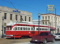
I am fairly new to trolley modelling myself, having wandered into it in the late 1990s - mostly on the strength of what was happening in my old hometown of Kenosha. I knew most of the players who got the thing going, and the history of everything around the line. After five years, their downtown is looking healthier - an amazing number of factory-worker liquid lunch joints have become wine bars! And the Corgis are always a big hit in Kenosha, with our most memorable operation being the three times we've set up inside the actual carbarn (1:48 scale on the left, 1:1 scale on the right). Of course, now I always have more projects than time, which is why a nice little job like this has such appeal. These cars are nice looking, relatively inexpensive, good running and practically indestructible. They stand up against far more expensive models pretty well, and are a great way into the hobby without going broke. At around $160 for a running car, nothing in O-Scale comes close.
|
