Photo Gallery - Model
Page 7
The work of Bill Becwar of Wauwatosa, Wisconsin.
Photos and wiring diagram by Bill Becwar. Click on the thumbnail to see the full size photo.
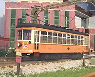
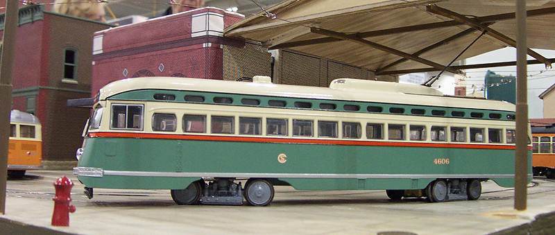
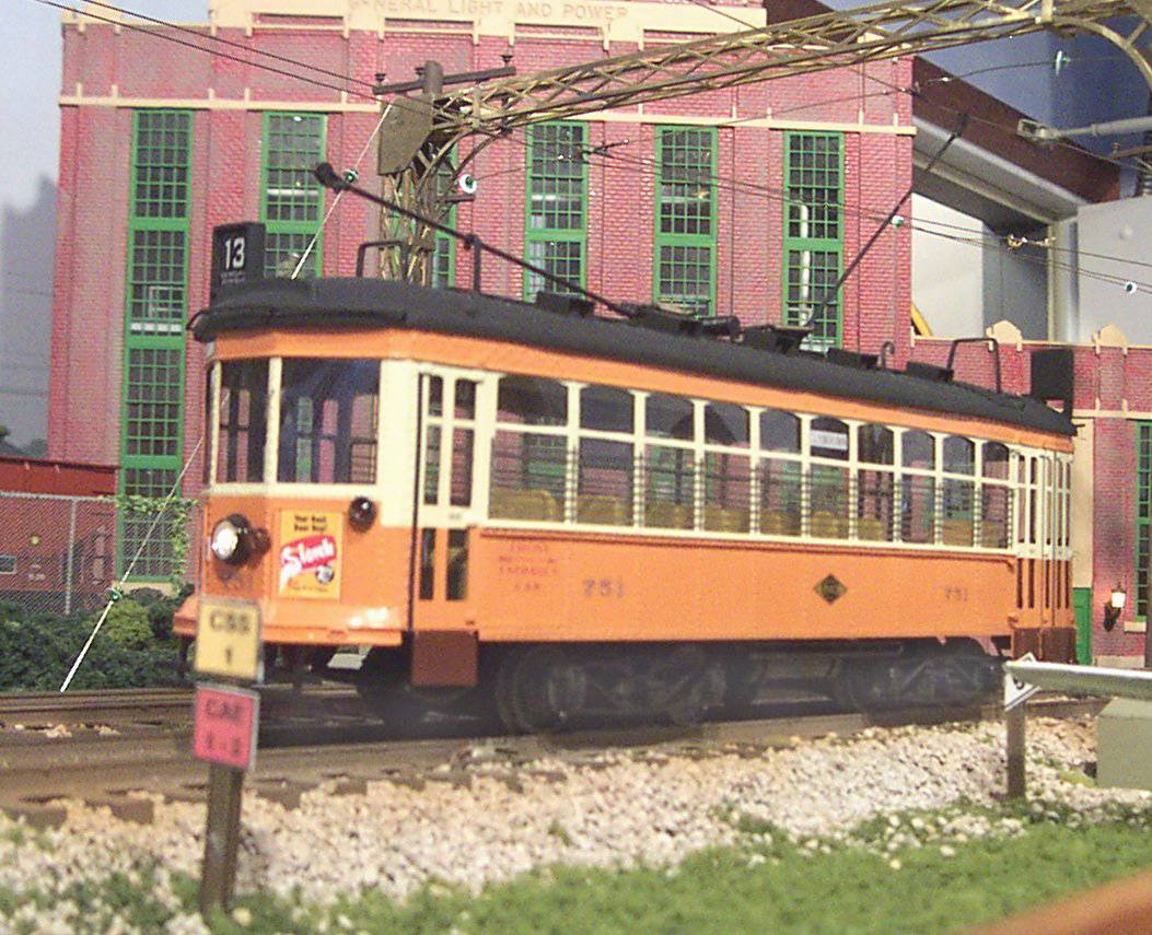
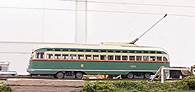 The Corgi conversion was done as a project to see just how simple I could power it and still have the ability to run on two-rail or overhead to produce a good-looking, inexpensive, practically indestructible car that the
kids can run. It represents the three-year-old Kenosha Electric Trolley line (which uses ex-Toronto PCCs). Q-Car trucks and poles, a couple of pieces of
hardware store metal and off it runs in one evening - even including a fairly The Corgi conversion was done as a project to see just how simple I could power it and still have the ability to run on two-rail or overhead to produce a good-looking, inexpensive, practically indestructible car that the
kids can run. It represents the three-year-old Kenosha Electric Trolley line (which uses ex-Toronto PCCs). Q-Car trucks and poles, a couple of pieces of
hardware store metal and off it runs in one evening - even including a fairly  well detailed interior. It needed very little tweeking or run in, just loosening the truck mounting nut to allow for our "less than perfect" trackage. The Corgi uses the Q PCC trucks, two-spring trolley pole, and the
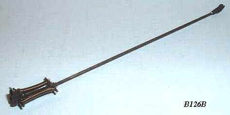
(B153) trolley hook, which is mounted on a wooden spacer as on the 1:1 scale Kenosha cars. Low-speed operation was perfect and extremely smooth - something we've come to expect from Q-Drives. It has power enough to pull scale buildings down the layout. well detailed interior. It needed very little tweeking or run in, just loosening the truck mounting nut to allow for our "less than perfect" trackage. The Corgi uses the Q PCC trucks, two-spring trolley pole, and the
(B153) trolley hook, which is mounted on a wooden spacer as on the 1:1 scale Kenosha cars. Low-speed operation was perfect and extremely smooth - something we've come to expect from Q-Drives. It has power enough to pull scale buildings down the layout.
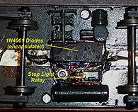
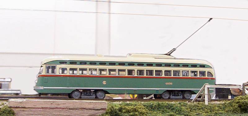
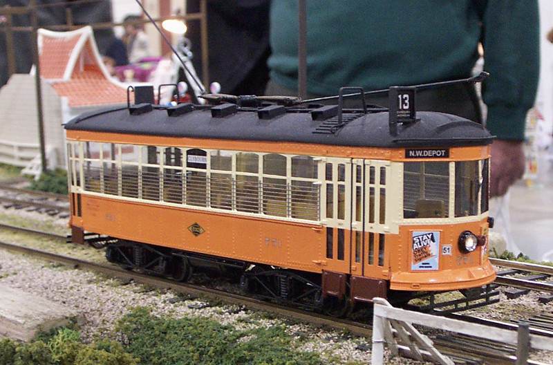
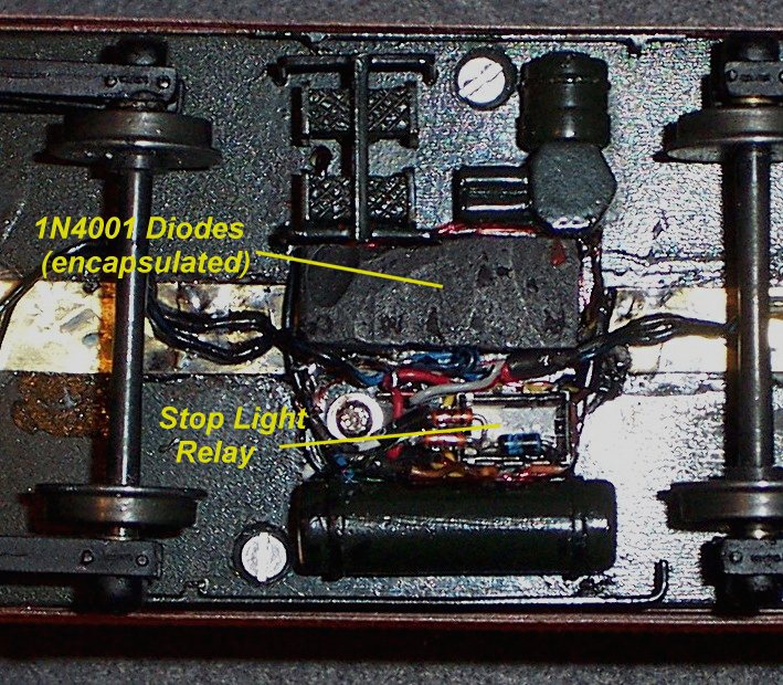
The 751 took lots longer to convert, but there is more to it as well. It 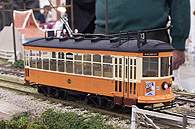 is a heavily modified St. Petersburg static model. The design goals were hidden wiring and electrics - as much as possible, smooth running and prototypical head and tail lights. Old hands around Milwaukee told me that these cars had a stop light that lit just as the car's doors opened. Designing a circuit to do this wasn't hard, but designing one that was both bi-directional and small enough to hide underneath the 750 was. The stop light is a drilled-out Milwaukee style light from Q-Car
(CS156) with a Walthers lens. The St. Petersburg headlight now has a clear lens to magnify the smallish is a heavily modified St. Petersburg static model. The design goals were hidden wiring and electrics - as much as possible, smooth running and prototypical head and tail lights. Old hands around Milwaukee told me that these cars had a stop light that lit just as the car's doors opened. Designing a circuit to do this wasn't hard, but designing one that was both bi-directional and small enough to hide underneath the 750 was. The stop light is a drilled-out Milwaukee style light from Q-Car
(CS156) with a Walthers lens. The St. Petersburg headlight now has a clear lens to magnify the smallish 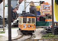 lamps required by the cast-resin St. Petersburg construction. lamps required by the cast-resin St. Petersburg construction.
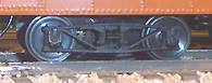
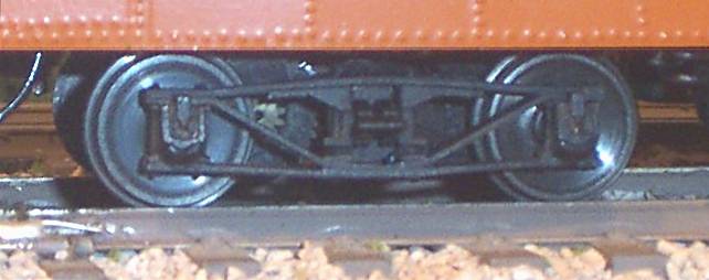
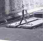
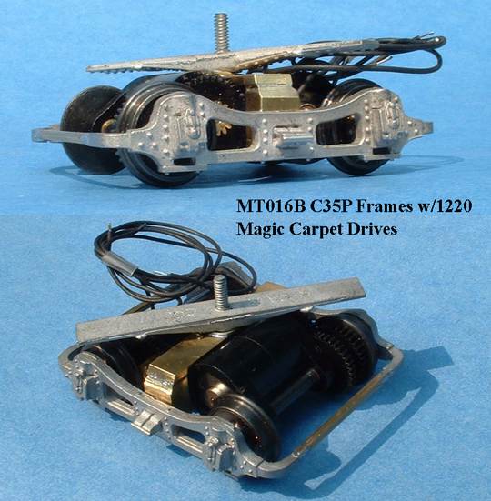
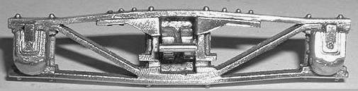
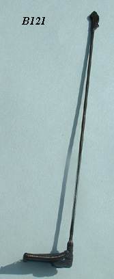
The trucks are NWSL Magic Carpets with 26" wheels mounted in modified Q-Car CS257 Laconia side frames (the triangle ends were cut off to look closer - and to clear the underbody equipment) . These trucks are a little long in wheelbase, but fitting the Magic Carpets still required filing a slot into the truck frame. [The correct trucks are now available - see (CS265) - Editor] The trucks pivot on steel T-Nuts set into the resin floor with shim-brass wear/contact surfaces. Floor height ended up about a scale 2" high because of shoe horning everything under the floor. Poles on the car are four-spring B121s - not a bad match to Milwaukee's, if a little shorter, but they worked great. By the way, we usually use a brass ferrule set into the roof for the pole mounting. This has the advantage of making the poles removable as well as allowing 360-degree pole spin with no back pressure from the wiring, and no broken wires inside the car body.

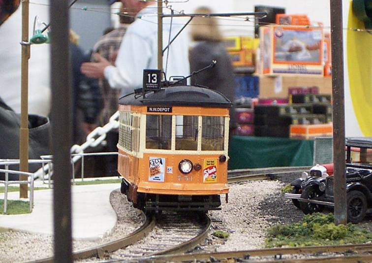
The St. Petersburg car ran nicely, with only a slight problem on some of the guard rail clearance on the NWSL drive gear. But this will be easy to fix as the guard rail is there only for appearance and the car would move over the interference, with a little noise as it walked on the gear. Our portable layout has a couple of 32' scale turns, but the short 750 car handled those easily.
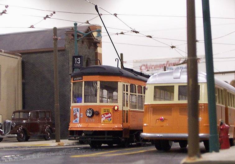
I calculated once that at a six-hour show in Kenosha last
Summer, one of our PCC cars with Q-Car trucks and trolley pole ran about 720
loops, or about 196 scale miles - the equivalent of about 4 REAL miles, or
more than twice around the actual Kenosha streetcar loop! It did this
without dewiring or derailing, which indicates pretty darned good running
gear since it was running on our three-section, portable layout that
has the above mentioned 32' radius (scale) turns.
Bill Becwar
|

|
Building the TMERL Stop Light Circuit Click to see diagram.
Car 751 Circuit Description
The Milwaukee 751 car model had minimal space for circuitry, so designing a stop light circuit that worked prototypically and could hide out of sight under the car was a challenge. As a traditional double-ended streetcar, the head and tail lights had to work properly regardless of the direction of travel. The basis of the circuit is the conventional "trolley reverse" circuit using a positive overhead wire and negative, grounded tracks. Though the circuit could be modified to run with two-rail, it would be somewhat more complex.
The diode stack of 1N4001s that provides the constant voltage for the lamps may look at first like it doesn't make sense. What makes it work is that each of the diodes blocks current flow completely in one direction, and conducts in the other direction with a constant voltage of about 0.7v across each diode. This is the characteristic that makes the constant voltage lighting work, producing about 1.4v across the lower two diodes in the circuit for each direction. The diodes immediately below the dashed line are steering diodes to make sure that only the headlight and tail light bulbs for the proper direction light up.
Below the dashed line, the diode stack drops the voltage to the motors by about 2.1 volts. Unfortunately, experimentation proved that it took more voltage than that to operate the stop light relay before the car started moving, so extra diode pairs were required. Depending on the exact motors and other components used, more pairs of diodes may be needed to delay the motor start. In the case of the car I was building, the motors started moving at about 1.5v, but the relay for the stop lights took about 3.75v to pull in. So it took a five diodes in each direction (or, 3.5v total) to provide the correct balance. This means the car starts rolling at around 5 volts, though the lights will be on from the time the power pack provides around 3 volts.
The stop light relay circuit contains two small steering diodes to provide the positive voltage from either trolley pole and a 2.4v zener diode to make the voltage cutoff very sharp. The zener seems "backwards" in the circuit because it is there to block completely when the voltage across it falls below 2.4 volts. Otherwise, the relay would stay pulled in down to about 0.5 volts - far below where the lights would have turned off. The relay used is an ultra miniature design intended for telecom use measuring only 3/8" x 1/4" x 3/16". All of the electronic components are available from the Digikey Company of Thief River Falls, MN .
The stop lights are wired to the normally closed contacts of the relay so they are disconnected once the voltage increases to the point where the relay pulls in. This provides the proper action of having the stoplight fully on until the car starts to move (on the prototype cars, the stop lights were on when the air brakes were set and doors open). The directional nature of the stack of 1N4001 diodes assures that only the lamps for the direction of motion will light up. Because of the steering diodes, the relay will only work with the overhead positive - if the polarity is reversed for some reason, the car's stop light for the given direction will stay on, but everything else works correctly.
Technically, the 5v relay used in this circuit is run at a voltage over its normal coil voltage, though its official continuous rating is 200% (10v). Since we never operate continuously at top speed on our model railroad, this was considered to be acceptable. If the car is to run at full voltage (12v or higher) for an extended periods, a small resistor would need to be wired in series with the 270 ohm relay coil - and more diodes would have to be added to the motor delay circuit to compensate.
A smaller or high efficiency motor might require some adjustment to the number of diodes, or might even require a load resistor (like a 12-14v lamp) to be wired in parallel with the motor to draw more current. For this car, the 280 mA (0.28 Amp) current draw of the pair of Magic Carpets worked fine.
I have been learning from every project I work on. My background in engineering helps a bit in construction and planning, but I've had lots of good advice from folks with long experience, particularly my fellow members of The Milwaukee Electric Railway & Transit Historical Society, Brian Siegl and Jack Gervais. They are also responsible for our portable model layout.
Bill Becwar
|
"Russian" TMER&L 751 Webster Safety Car.
An update on that "Russian" TMER&L 751 Webster Safety Car. Last year, I
got the St. Petersburg model running with modified Laconia sideframes
standing in for the TM M35AB's. The Laconia's looked and worked great, even
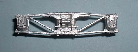
though very slightly longer in wheelbase. Now that Q-Car is producing the
actual M35 arch-bar sideframes, I decided it was time to update the car to
the exact prototype trucks. Result: the car looks just about perfect - and
works great. Only down side is that it isn't so easy to see the great detail
on the white metal truck castings since TM had the habit of painting
everything underfloor on these cars with their usual invisible black paint.
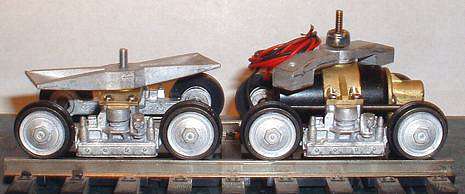
It did take considerable filing on the bolsters to get the Magic Carpets
III into the new, even more compact trucks, but the results are worth it.
Just as on the prototype, the power trucks are completely underfloor with
the traction motors entirely within the trucks. For technical reasons, I
had to go to 28" wheels on the new and improved version. Our club's
portable layout was designed with "compromise" guard rails on the city loop
trackage - necessary to allow both the old, Lionel-style giant wheel flanges
and current, close-to-prototype, 0.135" flanges to operate reliably on the
same trackage. But the slightly high guard rails inside the flangeway
turned out to be the same height as the drive gear on the Magic Carpet III
equipped with the 26" wheels. These ran OK, but, at a couple of points, you
could hear the streetcar "walking" along on the drive gear, which caused it
to slip and jerk a little. The extra 0.020" clearance is just enough to
avoid that problem. Now the Magic Carpets operate smoothly down to a
crawl - just what you want in a streetcar.
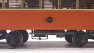
Two things that we've settled on lately that differ from what we've
heard elsewhere are T-nuts and sleeve-mounted trolley poles. Especially on
the resin-floored cars, it is awfully tough to get a screw to stay in them
without putting a nut on the inside of the car. The resin is too soft to
hold a tapped thread worth a darn.
 To avoid this, we've taken to epoxying
a #4 T-nut (available from model airplane suppliers) into the floor as the
truck mounting screw. The Q-Car bolsters normally are supplied with a #3
screw, but no one seems to make a T-nut in this size. This means drilling
out the bolster very slightly from a #3 [Editor: 3-48] to a #4 [Editor: 4-40] screw clearance, but the truck is then solidly attached to the floor with the screw going into steel threads on the car. It makes taking the trucks off for normal servicing far less nerve wracking, since the blind nut means you don't have to open the car every time you need to do a minor fix.
To avoid this, we've taken to epoxying
a #4 T-nut (available from model airplane suppliers) into the floor as the
truck mounting screw. The Q-Car bolsters normally are supplied with a #3
screw, but no one seems to make a T-nut in this size. This means drilling
out the bolster very slightly from a #3 [Editor: 3-48] to a #4 [Editor: 4-40] screw clearance, but the truck is then solidly attached to the floor with the screw going into steel threads on the car. It makes taking the trucks off for normal servicing far less nerve wracking, since the blind nut means you don't have to open the car every time you need to do a minor fix.
Alternate Pole Mounting: The other one is a trick I picked up from long-time TM modeller Jack
Gervais, though it probably didn't originate with him. That is to NOT mount
trolley poles using the supplied screws, but to cut a short brass sleeve to glue into the roof as a bushing and use a length of #2-56 threaded rod on the pole itself instead of a screw. Now the electrical connection can be soldered to the
sleeve - which never moves - and the pole can be removed or exchanged easily.
The result is that the wire to the trolley pole never breaks and the pole
turns with no back tension from the wire. The only caution
is to make the screw a little longer than the relatively thin roof sleeve or
you will be chasing the pole across the room when it dewires. With this
arrangement, I always remove the poles when transporting the models and
never have a problem with the poles or cars getting damaged.
Thanks to Q-Car for the great products that make trolley modelling far more enjoyable. The detail parts make realism possible, and give people a real
flavor of what these cars looked like and what they did - and do, in an
increasing number of cities. I wonder how long it will be before the kids
in this trolley hobby are asking us about the old days when San Diego ran
those boxy UD1s from the 1980s?
Bill Becwar -
The Milwaukee Electric Railway & Transit Historical Society
October 2004
|
All photos copyright Q-Car Company, Inc.
|
